
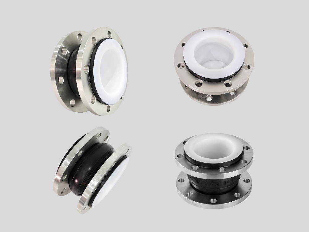
PTFE-Lined Rubber Expansion Joint
High-Performance Rubber Expansion for Industrial Excellence
PTFE-Lined Rubber Expansion Joint
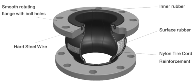
PTFE lining is used inside rubber expansion joints primarily to provide superior chemical resistance and media isolation that conventional rubber materials alone cannot achieve. While rubber expansion joints are excellent at absorbing vibration, compensating for pipe movement, and reducing noise, most rubber compounds have limitations when exposed to aggressive chemicals such as strong acids, alkalis, solvents, and certain industrial fluids. PTFE (Polytetrafluoroethylene) acts as a chemically inert barrier between the process media and the rubber body, significantly extending the service life of the expansion joint. From a material science perspective, PTFE has one of the lowest coefficients of friction and the highest chemical resistance among polymer materials. It is virtually unaffected by most industrial chemicals, including sulfuric acid, hydrochloric acid, sodium hydroxide, chlorine-containing media, and many organic solvents. By lining the inner surface of the rubber expansion joint with PTFE, direct chemical attack on the rubber is prevented, reducing swelling, cracking, hardening, and premature failure. In addition, PTFE lining improves cleanliness and reduces contamination risks, which is especially important in pharmaceutical, food processing, and high-purity chemical applications. The smooth PTFE surface minimizes residue buildup, scaling, and material adhesion, ensuring stable flow characteristics and easier system maintenance. Technically, the PTFE liner is designed to remain flexible and conform to the deformation of the rubber body, allowing the joint to retain its movement compensation capability without compromising chemical protection.
A PTFE-lined rubber expansion joint is specifically engineered to handle a wide range of aggressive, corrosive, and chemically active media that would otherwise degrade standard rubber expansion joints. Thanks to the PTFE liner, the joint can safely convey strong acids, alkalis, chemical solutions, solvents, seawater, industrial wastewater, and mixed chemical fluids commonly found in industrial processing systems. In chemical plants, PTFE-lined rubber expansion joints are widely used for sulfuric acid, nitric acid, phosphoric acid, hydrochloric acid, sodium hydroxide, potassium hydroxide, and chlorine-based media. In water treatment and desalination plants, they are suitable for treated water, brine, chemical dosing lines, and wastewater containing corrosive substances. The PTFE layer isolates the rubber body from continuous chemical exposure, preventing chemical permeation and material breakdown. It is important to note that while PTFE offers excellent chemical resistance, the overall performance still depends on system temperature, pressure, and flow conditions. High-temperature chemical media, abrasive particles, or high-velocity flow may require thicker PTFE linings or reinforced joint designs. Therefore, for critical applications, media composition, concentration, temperature, and operating pressure should always be evaluated during the selection process to ensure optimal performance and safety.
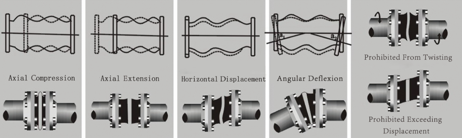
PTFE-lined rubber expansion joints are designed to compensate for multiple types of mechanical movement within piping systems, including axial, lateral, and angular displacement. These movements typically result from thermal expansion, equipment vibration, installation misalignment, pressure fluctuations, and operational stress. Axial movement compensation allows the joint to absorb expansion and contraction along the pipe axis caused by temperature changes or pressure variations. Lateral movement compensation addresses sideways displacement resulting from pipe settlement, foundation movement, or alignment errors. Angular movement compensation enables the joint to accommodate angular misalignment between connecting pipe sections, reducing stress on flanges and connected equipment. From a technical standpoint, the PTFE lining is engineered to deform together with the rubber body without cracking or delaminating. This ensures that movement compensation is not compromised while maintaining chemical resistance. Proper design and reinforcement layers within the rubber body ensure that the joint maintains structural integrity even under repeated cyclic movement, which is common in dynamic industrial environments.
The temperature and pressure capabilities of a PTFE-lined rubber expansion joint depend on several critical factors, including the rubber compound used, the thickness and construction of the PTFE liner, the reinforcement layers, and the flange connection design. PTFE itself can withstand a wide temperature range, typically from -50°C to +200°C, depending on application conditions. However, the rubber body usually defines the practical operating limits of the expansion joint. For most industrial applications, PTFE-lined rubber expansion joints are designed for moderate pressure systems, commonly PN10, PN16, or ANSI Class 150, depending on size and construction. Pressure ratings decrease as temperature increases, and continuous operation near maximum limits should be avoided to ensure long service life. Engineers must also consider pressure surges, vacuum conditions, and cyclic loading when specifying a PTFE-lined rubber expansion joint. In vacuum or negative pressure systems, additional reinforcement or vacuum support rings may be required to prevent collapse. Accurate evaluation of operating temperature, pressure fluctuations, and safety margins is essential to ensure reliable long-term operation.
Proper installation is critical to achieving optimal performance and longevity of a PTFE-lined rubber expansion joint. Incorrect installation can lead to premature failure, leakage, or damage to the PTFE lining. The joint should be installed without excessive pre-compression, extension, or torsion. Pipes must be correctly aligned before installation to avoid introducing unnecessary stress. Bolt tightening should be carried out evenly in a cross-pattern to ensure uniform gasket compression and prevent flange distortion. Over-tightening can damage the PTFE lining and restrict movement, while under-tightening may result in leakage. It is also essential to follow recommended torque values based on flange size and pressure class. Additionally, PTFE-lined rubber expansion joints should not be used to correct large misalignments or absorb loads beyond their design limits. They are intended to accommodate normal operational movement, not structural defects. Regular inspection after commissioning is recommended to check bolt tightness and ensure the joint operates within specified movement limits.
Customization Options for Flanges and Single Bellow
| Option | Flange Material | Flange Standards | Sphere (Bellow) Material |
|---|---|---|---|
| 1 | Cast Iron | ANSI (American National) | NR (Natural Rubber) |
| 2 | Carbon Steel | DIN (German Standards) | NBR (Nitrile Butadiene Rubber) |
| 3 | Stainless Steel | JIS (Japanese Standards) | EPDM |
| 4 | Brass | BS (British Standard) | CR (Chloroprene) |
| 5 | Aluminum Alloy | Chemical Industry Standards | FKM (Fluoroelastomer) |
| 6 | PVC | Marine Standards | Silicone |
| 7 | Other Materials | Custom Non-Standard | PTFE Lining |
Structure of Rubber Expansion Joint
Displacement Mode Diagram of Rubber Expansion Joints
Installation Diagram of PTFE-Lined Rubber Expansion Joint
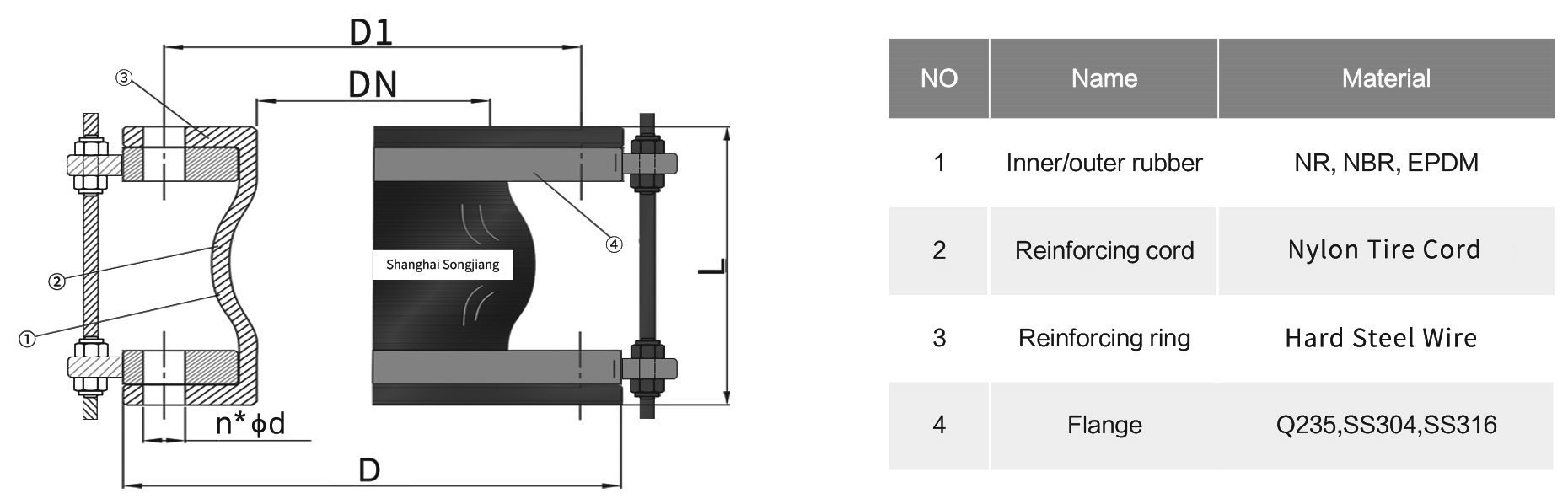
Parameter Table of PTFE-Lined Rubber Expansion Joint
| Nominal Diameter (DN) | Inch Size (“) | Length (L) mm | Flange Outer Diameter (OD) mm | Bolt Circle Diameter (PCD) mm | Hole Diameter (d) mm | Number of Bolts |
|---|---|---|---|---|---|---|
| DN32 | 1¼” | 95 | 135 | 100 | 18 | 4 |
| DN40 | 1½” | 95 | 145 | 110 | 18 | 4 |
| DN50 | 2″ | 105 | 160 | 125 | 18 | 4 |
| DN65 | 2½” | 115 | 180 | 145 | 18 | 4 |
| DN80 | 3″ | 135 | 195 | 160 | 18 | 8 |
| DN100 | 4″ | 150 | 215 | 180 | 18 | 8 |
| DN125 | 5″ | 165 | 245 | 210 | 18 | 8 |
| DN150 | 6″ | 180 | 280 | 240 | 22 | 8 |
| DN200 | 8″ | 200 | 335 | 295 | 22 | 8 |
| DN250 | 10″ | 225 | 405 | 355 | 26 | 12 |
| DN300 | 12″ | 250 | 460 | 410 | 26 | 12 |
| DN350 | 14″ | 250 | 520 | 470 | 26 | 16 |
| DN400 | 16″ | 250 | 580 | 525 | 30 | 16 |
| DN450 | 18″ | 250 | 640 | 585 | 30 | 20 |
| DN500 | 20″ | 250 | 715 | 650 | 33 | 20 |
| DN600 | 24″ | 260 | 840 | 770 | 36 | 20 |
| DN700 | 28″ | 280 | 910 | 840 | 36 | 24 |
| DN800 | 32″ | 300 | 1020 | 950 | 39 | 24 |
| DN900 | 36″ | 320 | 1120 | 1050 | 39 | 28 |
| DN1000 | 40″ | 340 | 1255 | 1170 | 42 | 28 |
| DN1200 | 48″ | 360 | 1485 | 1390 | 48 | 32 |
